

🎓 Dr. Freemo  🇳🇱
@freemo@social.cleverlibre.org
🇳🇱
@freemo@social.cleverlibre.org
- UFoI Member
- http://UFoI.org/u/freemo/
- Website
- http://JeffreyFreeman.me
- Gitlab
- https://git.qoto.org/freemo
Admin
Jeffrey Phillips Freeman
Innovator & Entrepreneur in Machine Learning, Evolutionary Computing & Big Data. Avid SCUBA diver, Open-source developer, HAM radio operator, astrophotographer, and anything nerdy.
Born and raised in Philadelphia, PA, USA, currently living in Utrecht, Netherlands, USA, and Thailand. Was also living in Israel, but left.
Pronouns: Sir / Mister
(Above pronouns are not intended to mock, i will respect any persons pronouns and only wish pronouns to show respect be used with me as well. These are called neopronouns, see an example of the word "frog" used as a neopronoun here: http://tinyurl.com/44hhej89 )
A proud member of the Penobscot Native American tribe, as well as a Mayflower passenger descendant. I sometimes post about my genealogical history.
My stance on various issues:
Education: Free to PhD, tax paid
Abortion: Protected, tax paid, limited time-frame
Welfare: Yes, no one should starve
UBI: No, use welfare
Racism: is real
Guns: Shall not be infringed
LGBT+/minorities: Support
Pronouns: Will respect
Trump: Moron, evil
Biden: Senile, racist
Police: ACAB
Drugs: Fully legal, no prescriptions needed
GPG/PGP Fingerprint: 8B23 64CD 2403 6DCB 7531 01D0 052D DA8E 0506 CBCE
Joined Jul 2018
So I recently got a few thousand boards printed up for my protoboard design. Tested them on a few circuits and im amazed how well they work. I'm writing the datasheet now and we will begin selling on digikey, mouser, and many other big names soon.
In the meantime any EE people out there want a free board? We are going to hand out a few hundred for free to get people interested.
Here are some past posts I made about it for some background info. I've also attached an image of the final boards.
https://qoto.org/@freemo/101518455796695415
https://qoto.org/@freemo/101517564046276857
https://qoto.org/@freemo/101471853619646546
#RF #EE #Electronics #Engineering #Science #ElectricalEngineering #RFEngineering #HAM #hamradio


My favorite alloy is copper-gold alloy, here is why:
Copper is dissolved easily by acid where gold i not. Therefore if you rub any such alloy with acid you can eat away the copper leaving just the gold. This creates a similar effect as gold plating where a thin layer of pure gold is on the outside and the whole object looks like pure gold.
Of course gold is soft so even though the whole alloyed object is pretty strong thanks to the copper the thin outer layer is soft and wears away over time easily. When it goes from gold back to a rose-gold copper color just rub it down with a little more acid and it turns gold again.
Its much cheaper than pure gold but looks just as nice and is easily cleaned up. Its really win win in many ways.
Interesting note, the romans used to use this for their armor. Since they would clean it off with acetic acid from vinegar it looks like pure gold and thus was impressive on the battlefield to see. The gol shine would wear off fast from battle but was easily restored in the next cleaning.
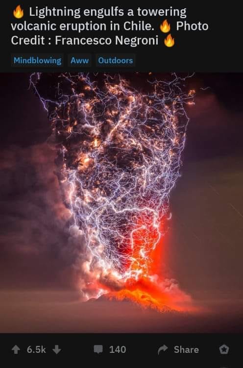

Love this Gal's solar weather reports each week. Since I do a lot of Radio propagation stuff I really need to remain up to date.
To help some of the newcomers make connections: name 5-7 things that interest as tags so they are searchable. Then boost this post or repeat its instructions so others know to do the same. Add #introductions to the post.
#Photography
#Astrophotography
#Netherlands
#utrecht
#QuantumPhysics
#Philosophy
#Science
#Nature
#SCUBA
#Chemistry
#occult
#Biology
#bioalgorithms
#Programming
#ClassicalLiberal

Still one of my favorite #Astrophotography shots I ever took. It shows the core details of The Great Nebula in Orion. You can even see the 4 separate stars in the trapezium.


Attached are some older pictures of blackholes that predate the one released today, they are real, not simulations. Enjoy.
Just a reminder. Today's "first-ever" picture of a blackhole is not the first-ever. We have countless pictures of blackholes. This is just the first time we have been able to resolve the event horizon such that it takes up more than a single pixel. But like with all blackholes the blackhole itself is invisible and all you can see is the gravitational lensing around it. Something we have had for decades now.
It isnt the first ever photo of a blackhole, it is just the highest resolution of a blackhole we have.

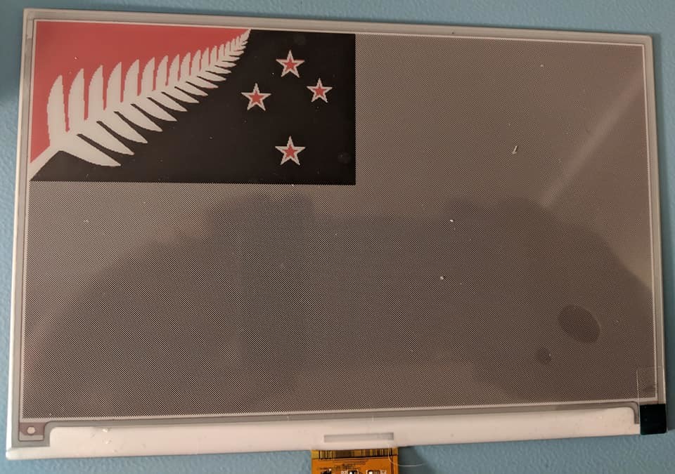
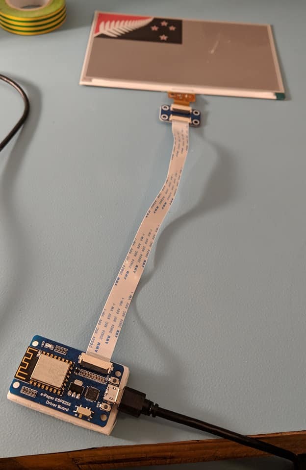
Now that I finally got my Electrical Engineering workbench in place I had some time to work on coding up a e-ink display. I finally got it successfully displaying images. This display is 7.5 inches and can do red black and white.
#electronics #EE #ElectricalEngineering #Engineering #Science
An image showing how the protoboard I designed is laid out as well as a picture of the printed board and my Frequency Counter design soldered to it as an example. I also attached the schematic for reference.
#RF #EE #Electronics #Engineering #Science #ElectricalEngineering #RFEngineering #HAM #hamradio


The first draft of the PCB protoboard I designed arrived. It is more beautiful than I could have imagined.
#RF #EE #Electronics #Engineering #Science #ElectricalEngineering #RFEngineering #HAM #hamradio
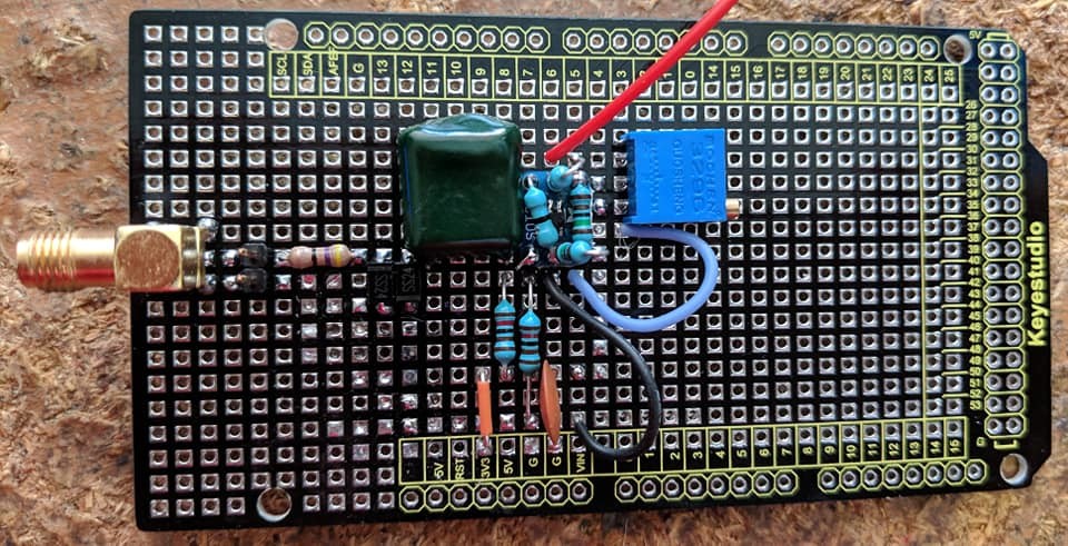
The latest version of my frequency counter prototype using a Manhattan style construction.
#RF #EE #Electronics #Engineering #Science #ElectricalEngineering #RFEngineering #HAM #hamradio

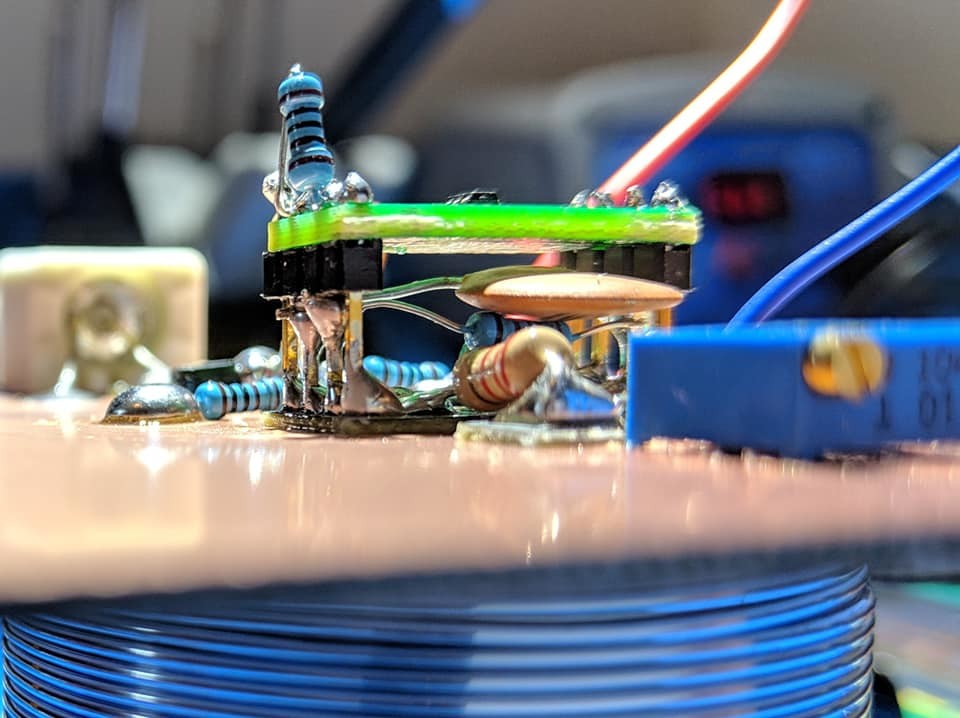
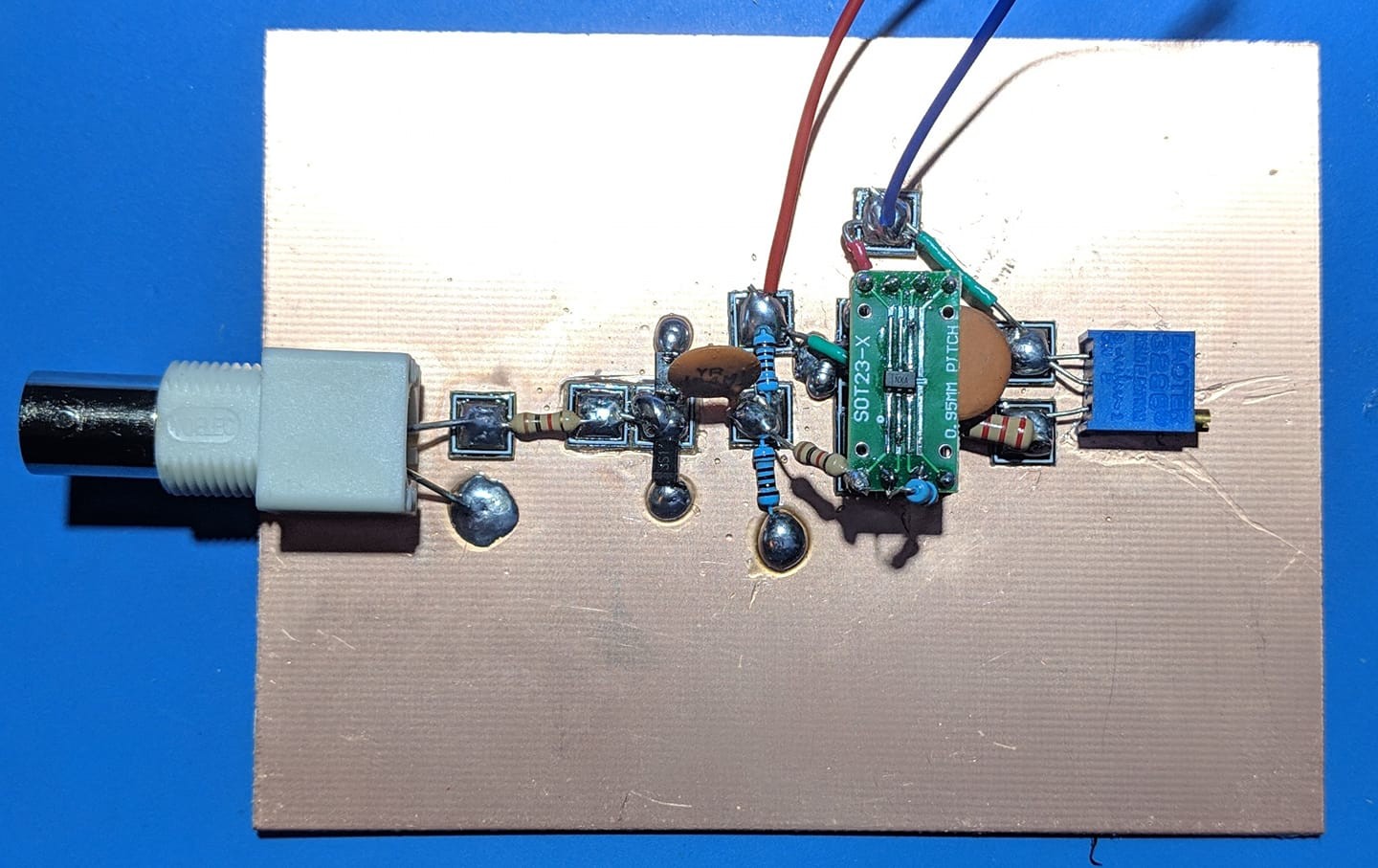
There is a sort of beauty in the order and chaos of a prototype design.
Just finished soldering together this frequency counter frontend.
#RF #EE #Electronics #Engineering #Science #ElectricalEngineering #RFEngineering #HAM #hamradio

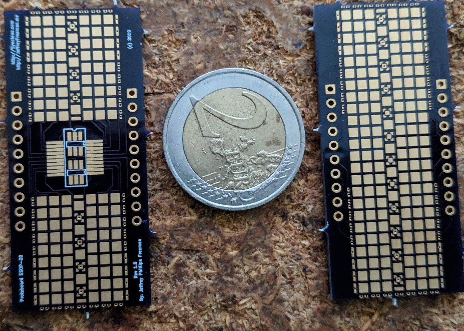
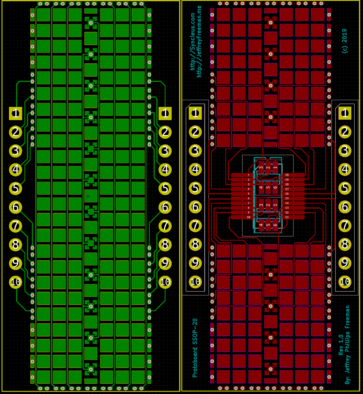
After several more hours of cleanup the Prototyping SMT board I've been working on is finally done. I attached both sides of the board below.
Here is a link if you want to order a few for yourself. If anyone is really interested I can even send a few out for free to try it out: http://dirtypcbs.com/store/designer/details/freemo/6230/smt-smd-prototyping-board-tssop-20-sop-20-sot-23-6
I havent decided yet if I want to make this open-source. I probably will.
It can act as a simple breakout board for either a single SSOP-20 or x2 SOT-23-6 chips. To use it as a normal breakout just use solder to bridge the 20 connectors on the right and left and sides of the board and it will be a normal breakout (which each pin on the chip going to one of the header pins directly).
Here is the full description.
However there is also a SMT grid on the front and back so you can solder a full circuit onto the chip and arbitrarily have any point in the circuit wired to the various pins. Which makes for very handle little modules you can solder up and reuse.
I also added two power rails for ground and VCC down the middle with vias to both sides of the board. I also added other connectors around the edge that add in vias and wires connections to the opposite side of the board. Should be very useful.
One other little hidden feature is the spacing. Most of the pads are the perfect size to fit most two terminal SMT components (x4 0603 components can solder onto a single pad). But because the pads down the middle are offset it is also very easy to solder on SOT-23 connectors that have 3 terminals. So you really can solder almost any sort of SMT components on here.
Next step will be to build a larger protoboard that can accept modules like this and similar to create more advanced circuits.
Attached are images of the top and back of the design.
#RF #EE #Electronics #Engineering #Science #ElectricalEngineering #RFEngineering #HAM #hamradio
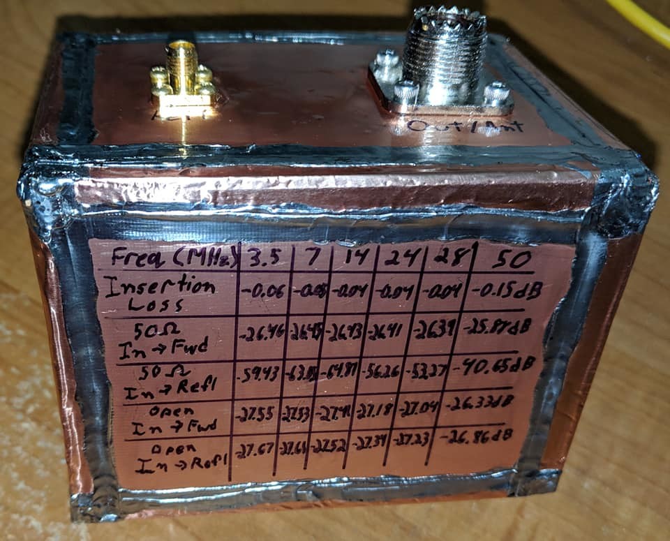
Cleaned up my Directional Coupler project. Labeled the ports and even added the electrical characteristics at different frequencies on the bottom. I then added a coat of lacquer resin to seal in that beautiful copper color (which otherwise would go brown as it oxidized).
The final result has a sort of beauty to it.
#RF #EE #Electronics #Engineering #Science #ElectricalEngineering #RFEngineering #HAM #HamRadio

If anyone is curious here are the characteristics of the Directional Coupler I just posted. The top line is the dBm on the forward port and the bottom line is the dBm on the REFL port for a 0dBm input signal. The markers for the common radio bands.
#RF #EE #Electronics #Engineering #Science #ElectricalEngineering #RFEngineering #HAM #HamRadio

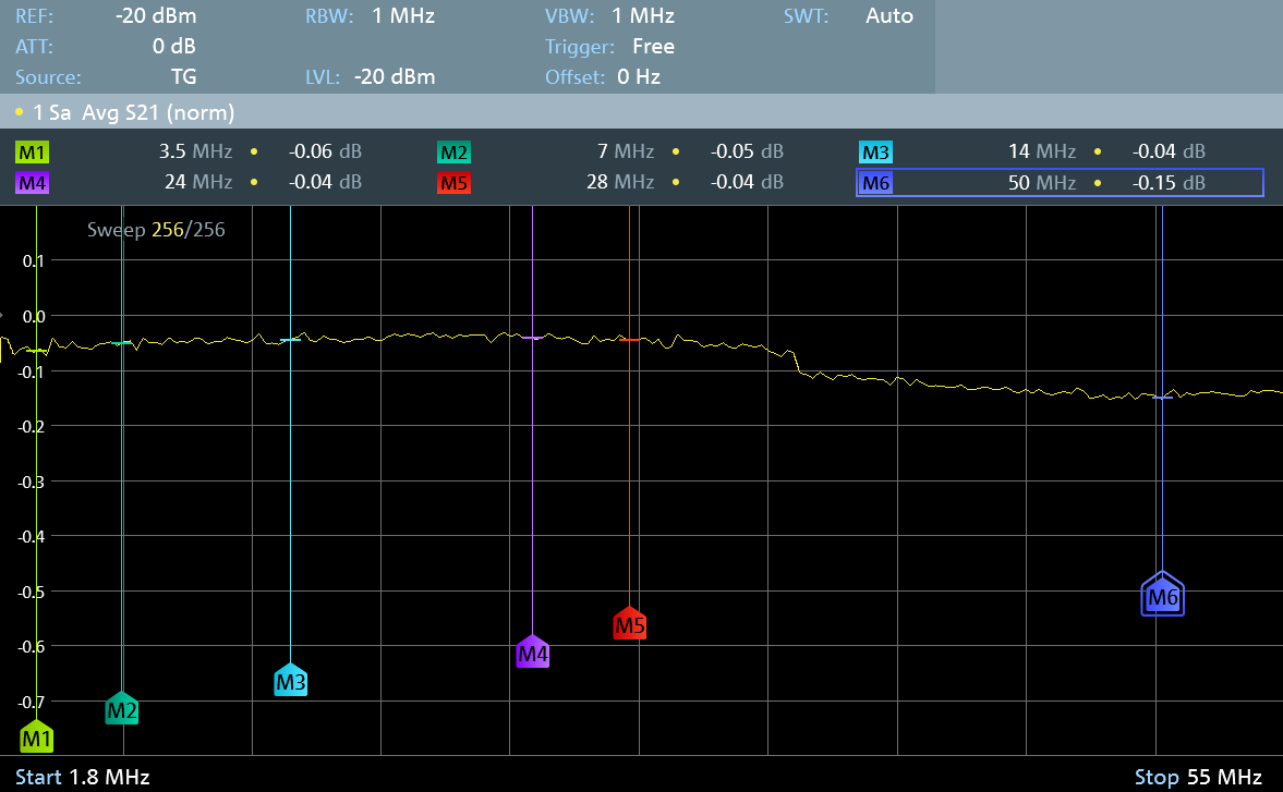
Woot, just tested the Insertion Loss on the directional Coupler I built. It has an amazing -0.05dB IL on most frequencies except 50MHz where it is still only -0.15dB!
#RF #EE #Electronics #Engineering #Science #ElectricalEngineering #RFEngineering #HAM #HamRadio
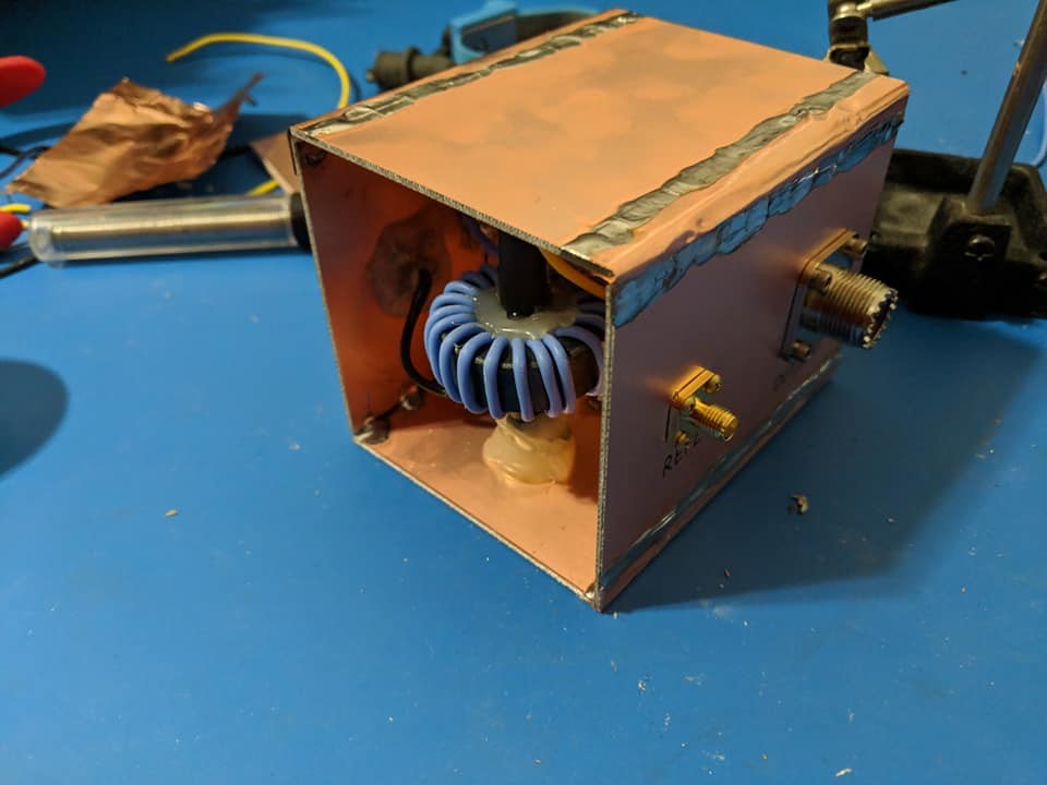
I finally had the nerve to seal her up. Next I am going to clean up the outside and put a coat of laquer on her before she begins to get a patina.
#RF #EE #Electronics #Engineering #Science #ElectricalEngineering #RFEngineering #HAM #HamRadio
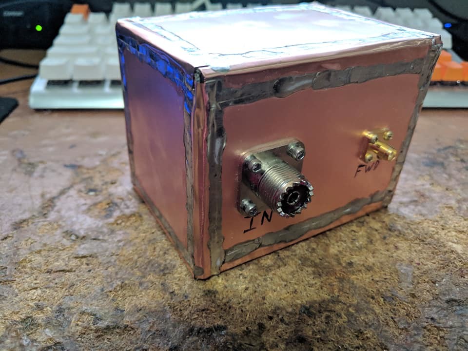
Started the final draft of the directional Coupler. Building in extra levels of shielding and a 20:1 winding ratio. I'm stoked to finally have the design locked down
#RF #EE #Electronics #Engineering #Science #ElectricalEngineering #RFEngineering #HAM #HamRadio


- UFoI Member
- http://UFoI.org/u/freemo/
- Website
- http://JeffreyFreeman.me
- Gitlab
- https://git.qoto.org/freemo
Admin
Jeffrey Phillips Freeman
Innovator & Entrepreneur in Machine Learning, Evolutionary Computing & Big Data. Avid SCUBA diver, Open-source developer, HAM radio operator, astrophotographer, and anything nerdy.
Born and raised in Philadelphia, PA, USA, currently living in Utrecht, Netherlands, USA, and Thailand. Was also living in Israel, but left.
Pronouns: Sir / Mister
(Above pronouns are not intended to mock, i will respect any persons pronouns and only wish pronouns to show respect be used with me as well. These are called neopronouns, see an example of the word "frog" used as a neopronoun here: http://tinyurl.com/44hhej89 )
A proud member of the Penobscot Native American tribe, as well as a Mayflower passenger descendant. I sometimes post about my genealogical history.
My stance on various issues:
Education: Free to PhD, tax paid
Abortion: Protected, tax paid, limited time-frame
Welfare: Yes, no one should starve
UBI: No, use welfare
Racism: is real
Guns: Shall not be infringed
LGBT+/minorities: Support
Pronouns: Will respect
Trump: Moron, evil
Biden: Senile, racist
Police: ACAB
Drugs: Fully legal, no prescriptions needed
GPG/PGP Fingerprint: 8B23 64CD 2403 6DCB 7531 01D0 052D DA8E 0506 CBCE
Joined Jul 2018
