
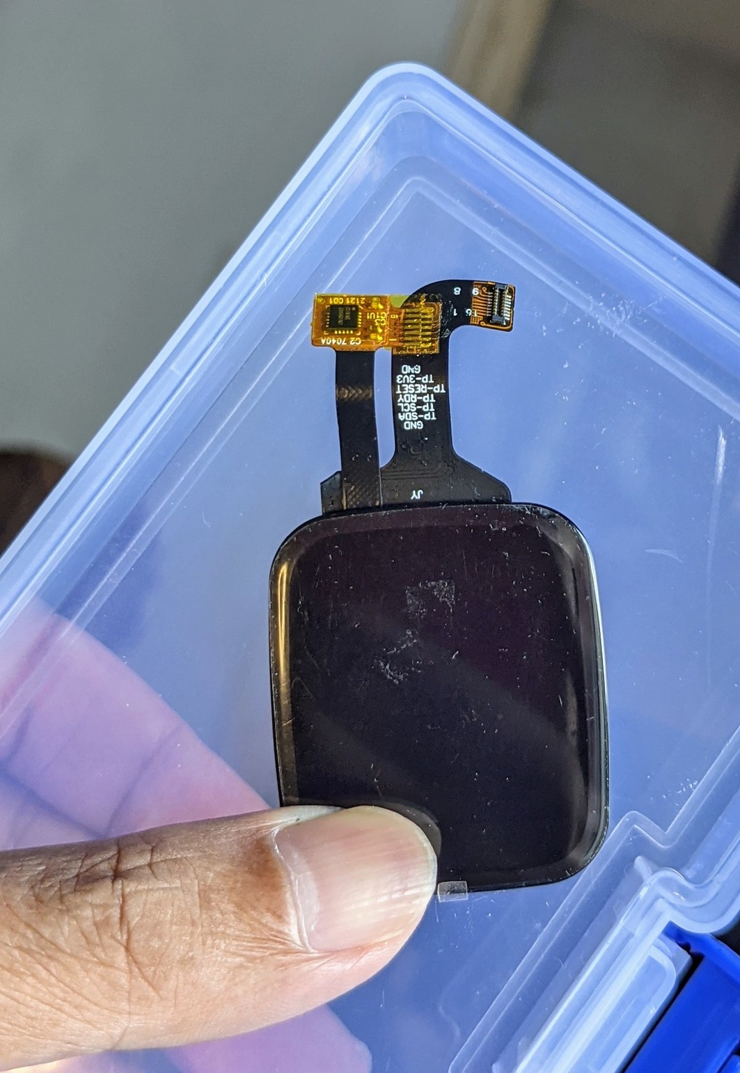
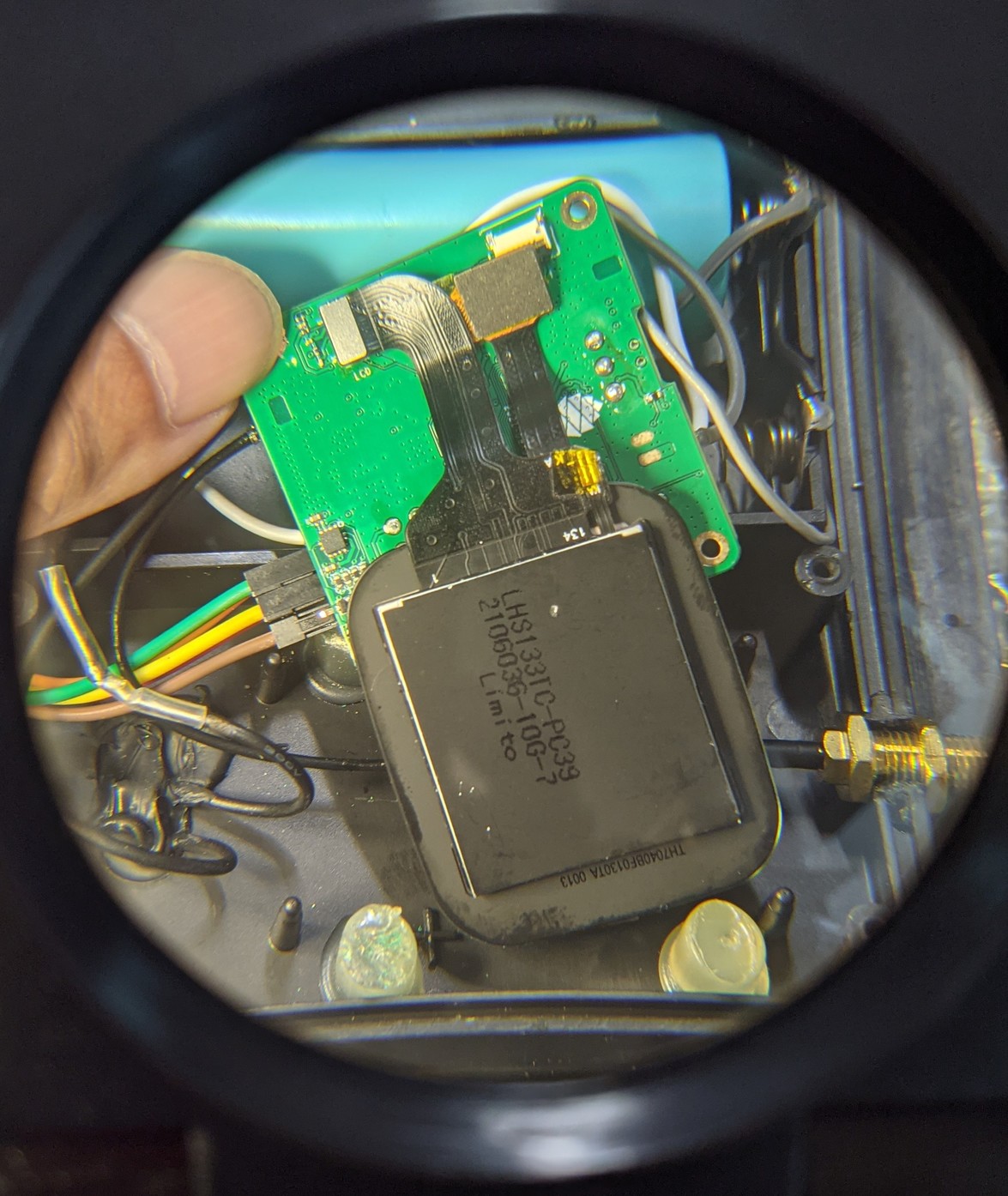
Super familiar touchscreen ... Will it connect with #PineDio Stack? 🤔
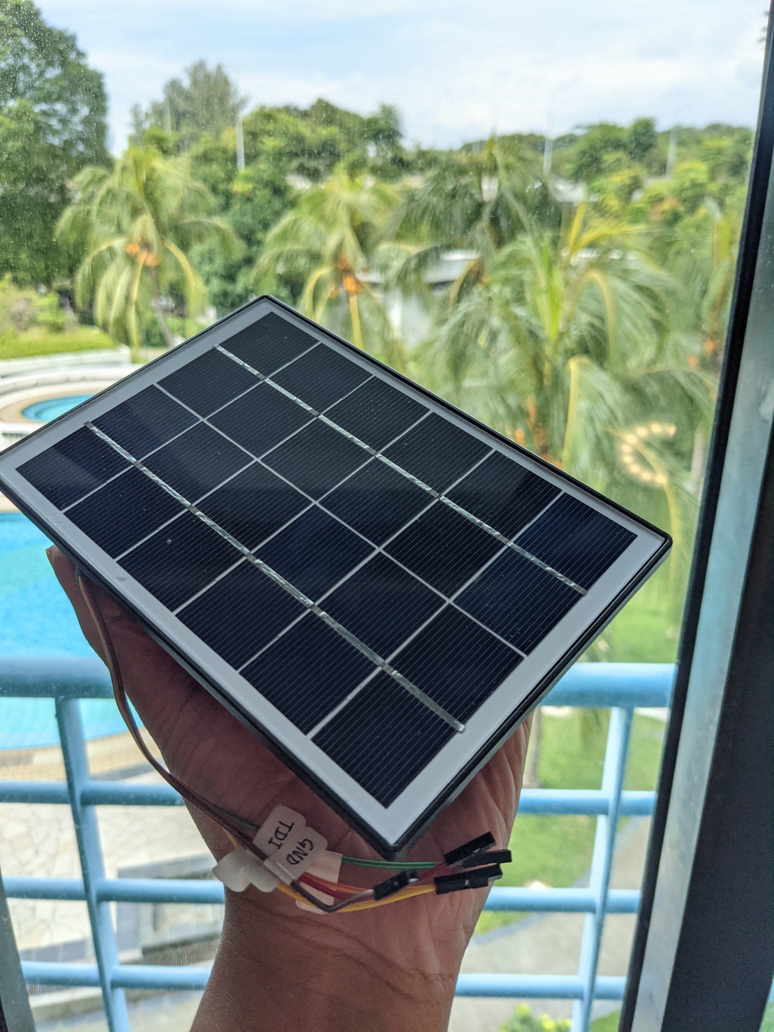
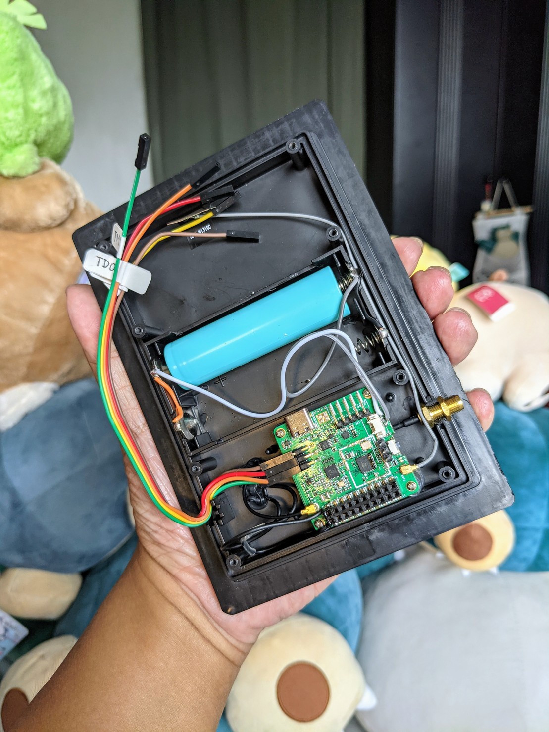
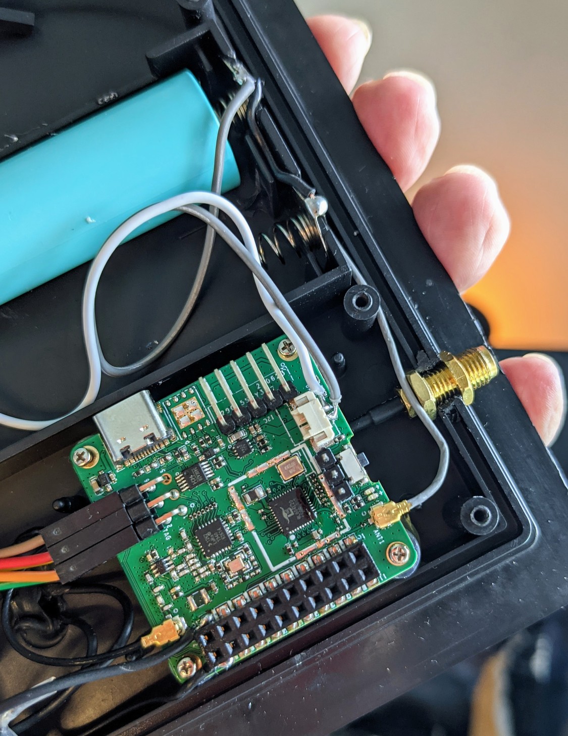
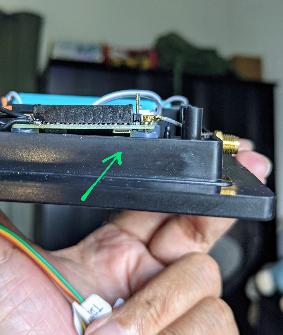
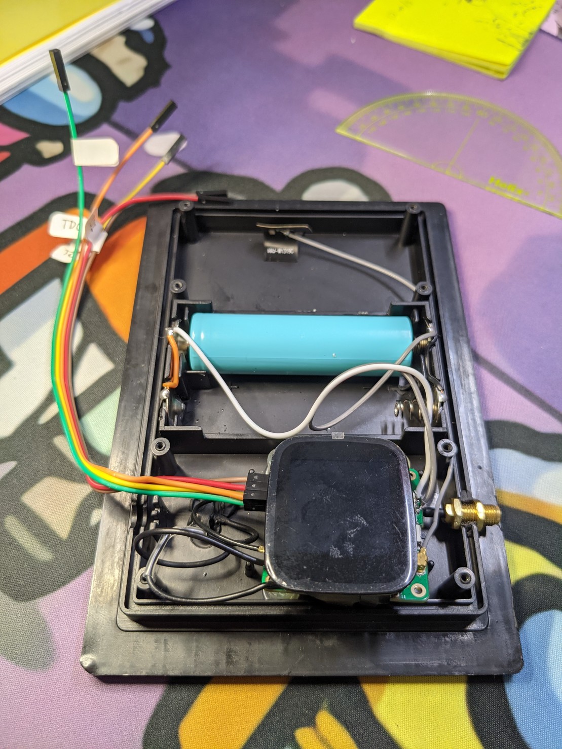
Voilà! Solar Panel with Touchscreen inside 😂
BL602 Firmware runs OK on PineDio Stack #BL604 @PINE64 ... Here's our Blinky Firmware
https://github.com/lupyuen/bl_iot_sdk/blob/3wire/customer_app/pinedio_blinky/pinedio_blinky/demo.c
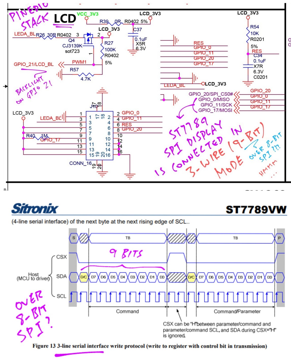
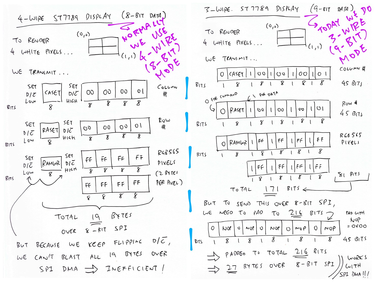
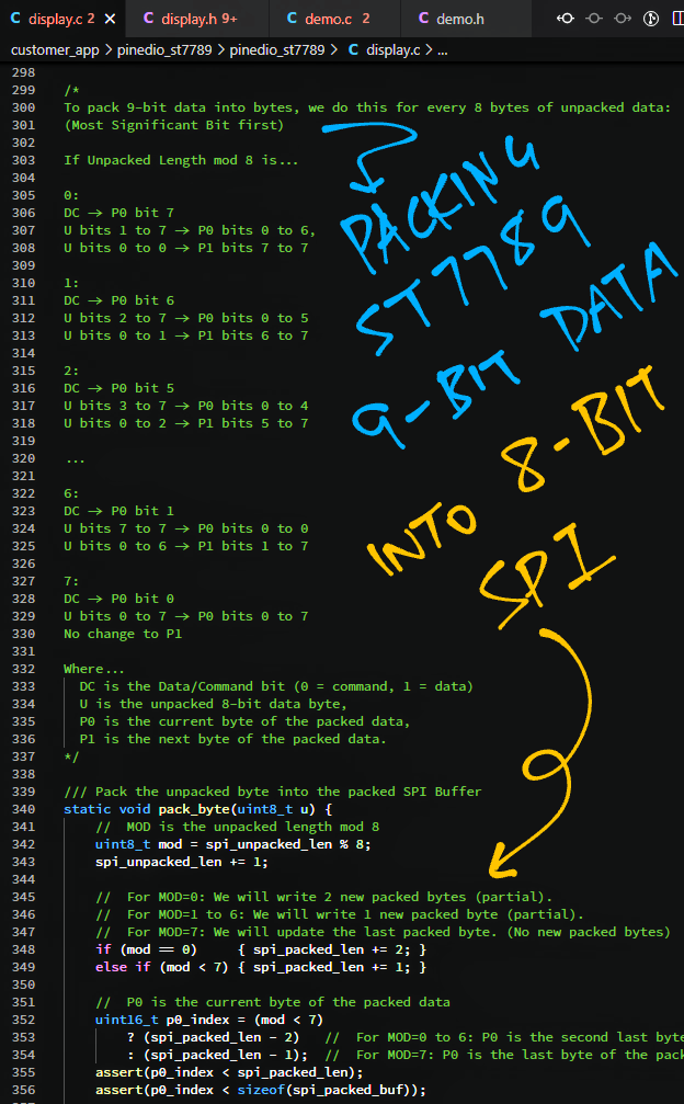
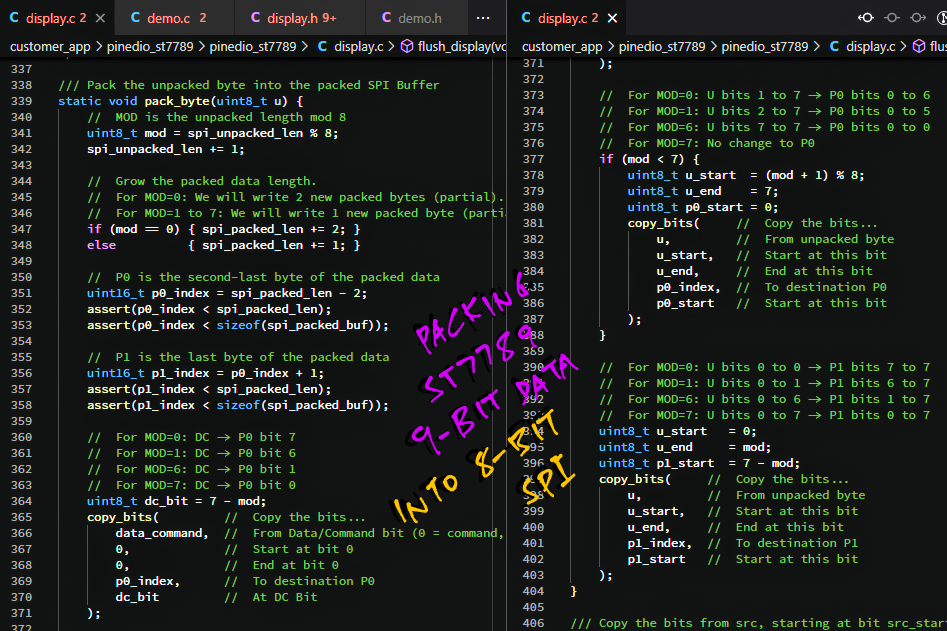
Normally we talk to #ST7789 SPI Display in 4-Wire (8-bit) Mode ... But today we do 3-Wire (9-bit) Mode ... With a sneaky packing hack
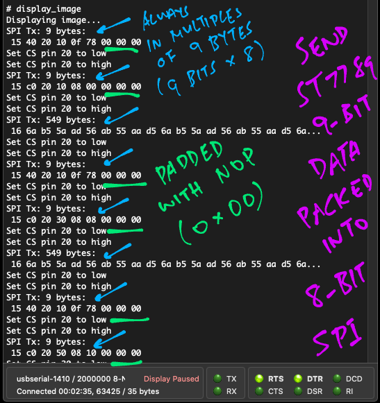
We're sending SPI data to #ST7789 in multiples of 9 Bytes ... Due to the 9-bit packing
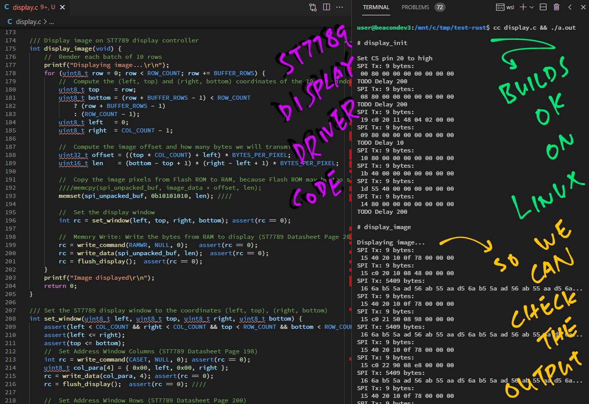
Since our #ST7789 Driver Code is in C, let's test it locally on Linux!
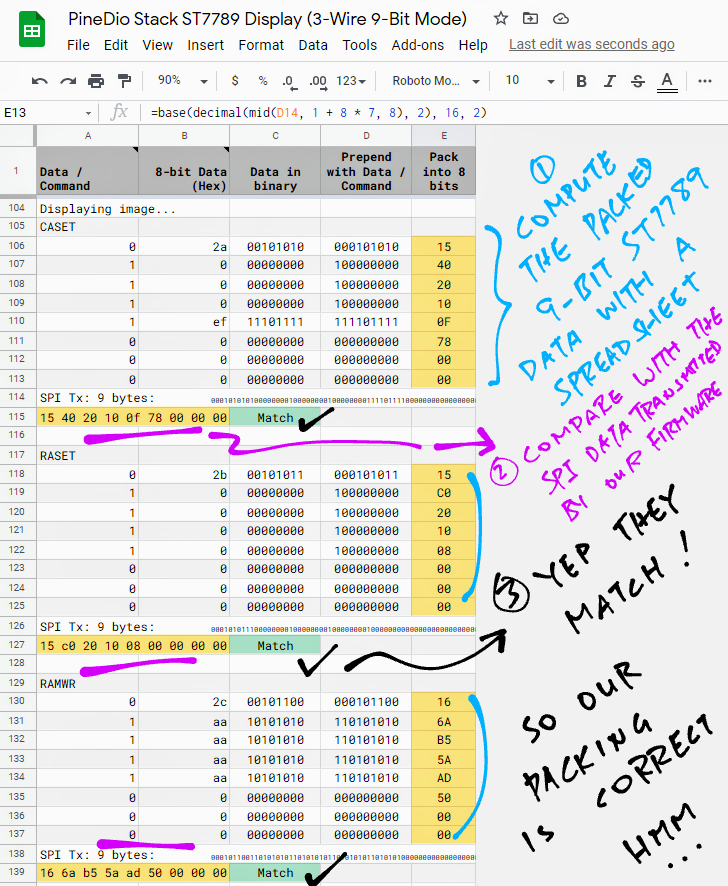
Verifying the packed #ST7789 9-bit data with a spreadsheet ... Our packing is indeed correct 🤔
https://docs.google.com/spreadsheets/d/1Qy0MjU79s__wzTAFwpTYUUIzLWcrFnKCrvvo_rHamiE/edit?usp=sharing
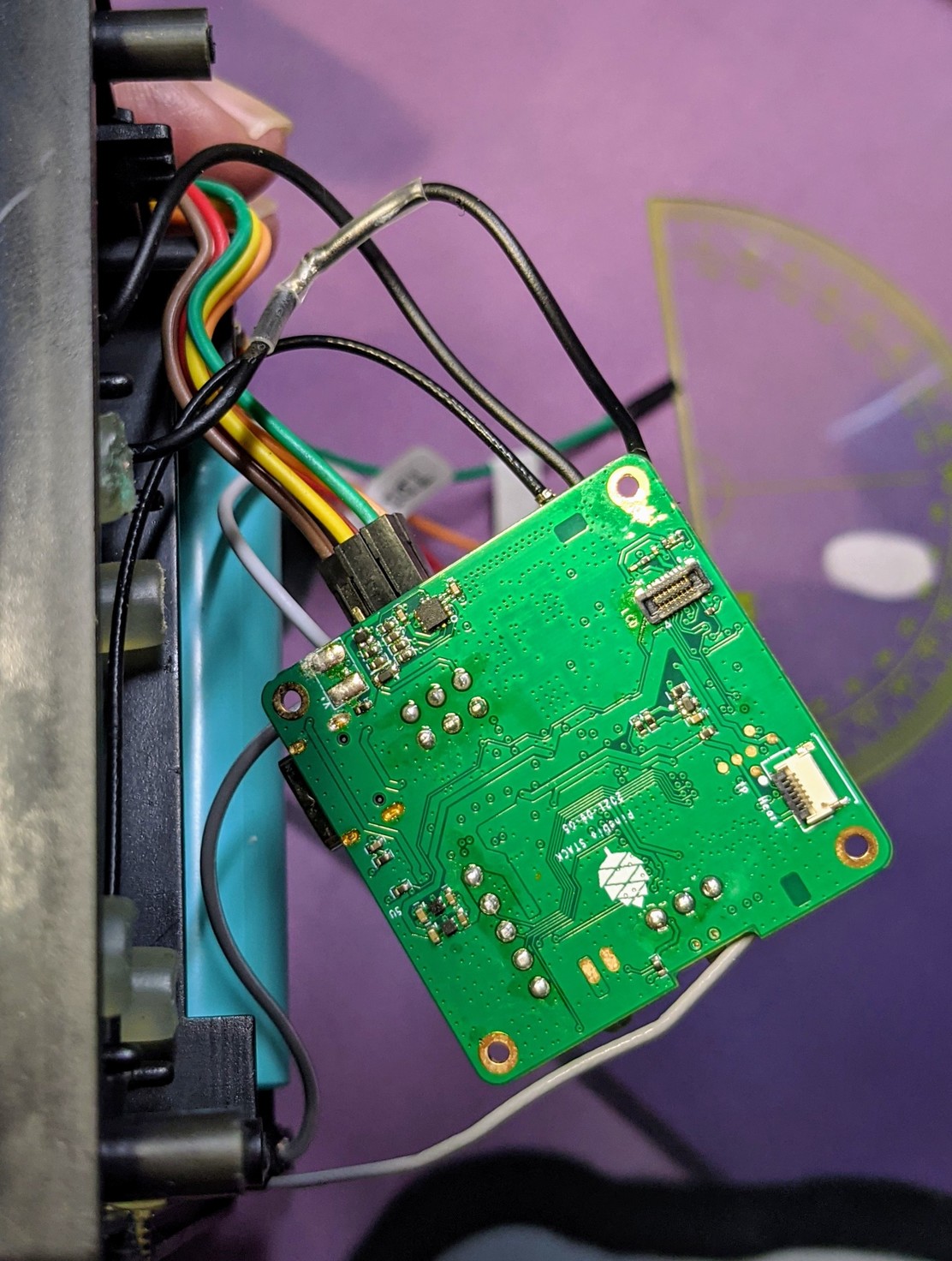
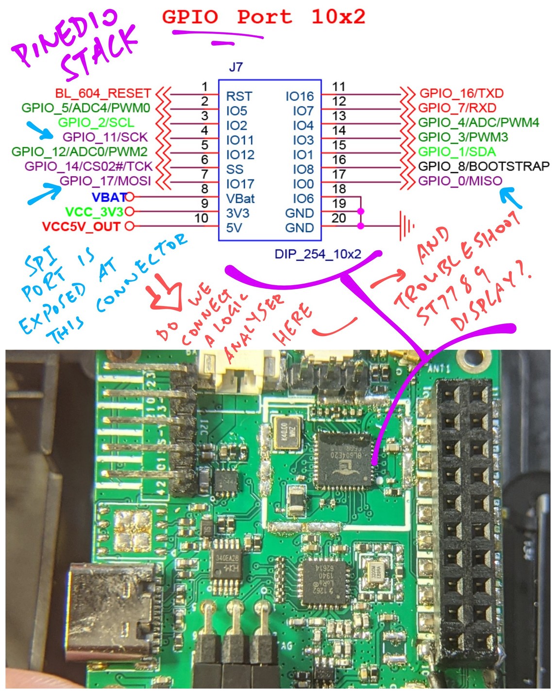
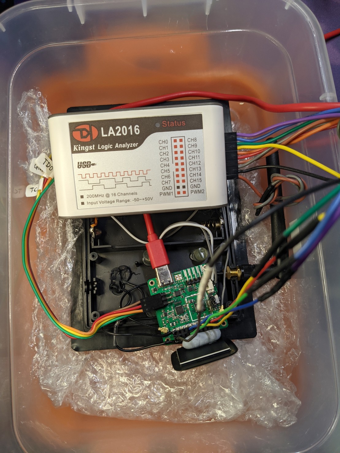
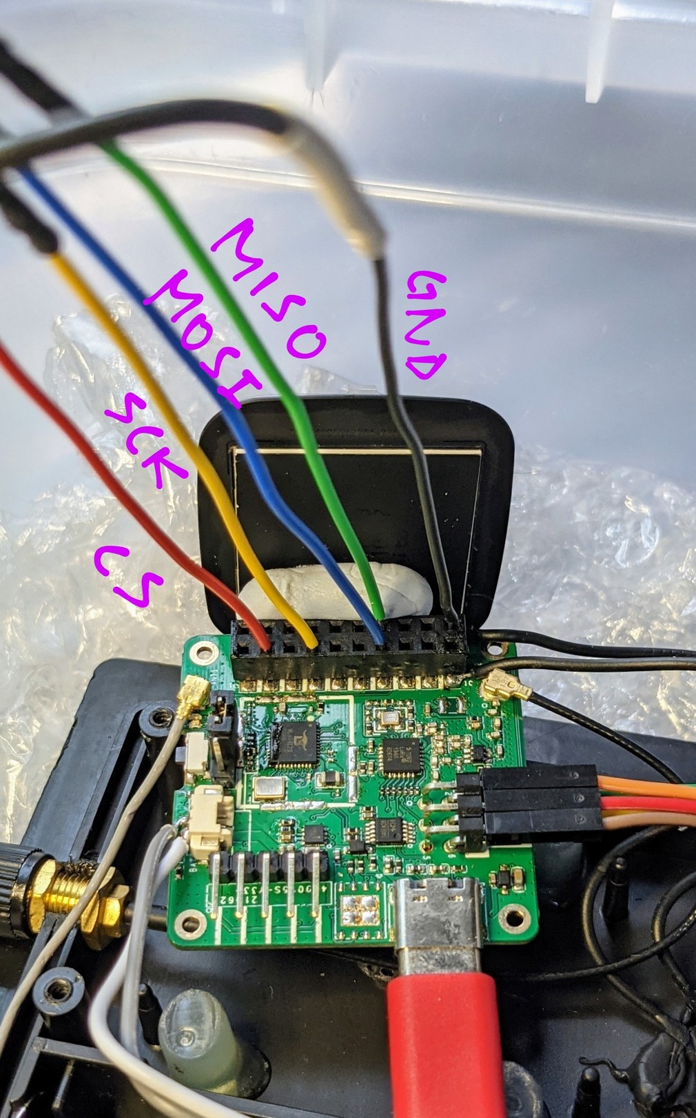
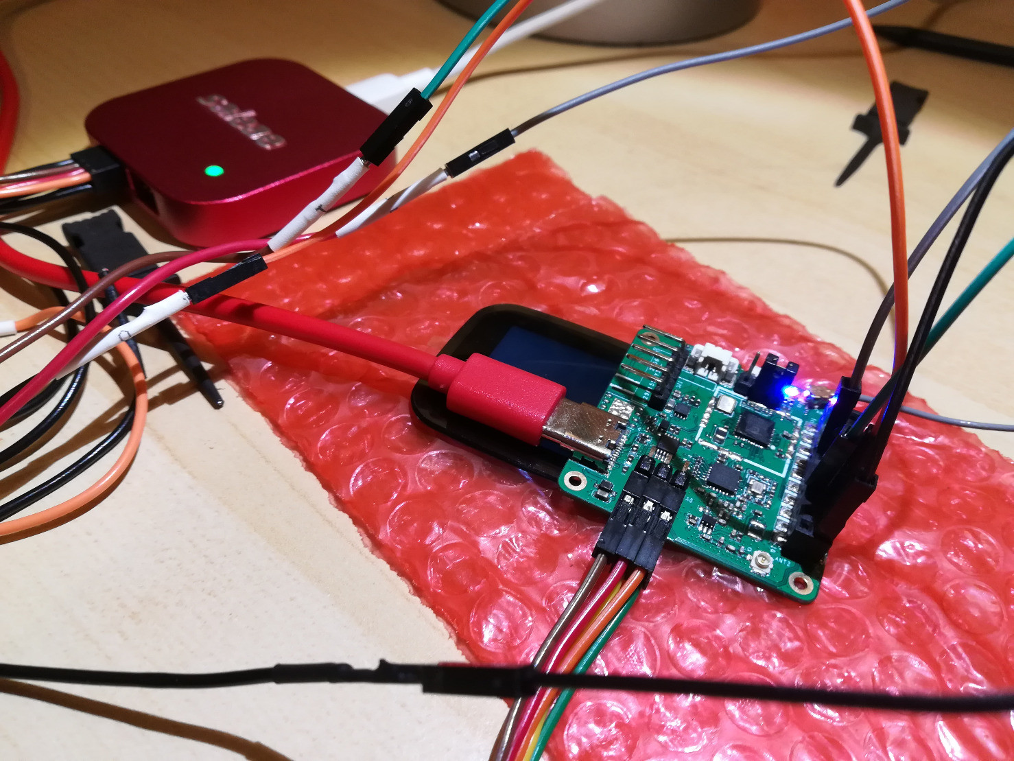
#PineDio Stack SPI Port is exposed on the GPIO Connector ... So we connect our Logic Analyser there
ST7789's CS Pin (GPIO 20) is not exposed on #PineDio Stack's GPIO Connector ... So we use GPIO 5 to Shadow the CS Pin
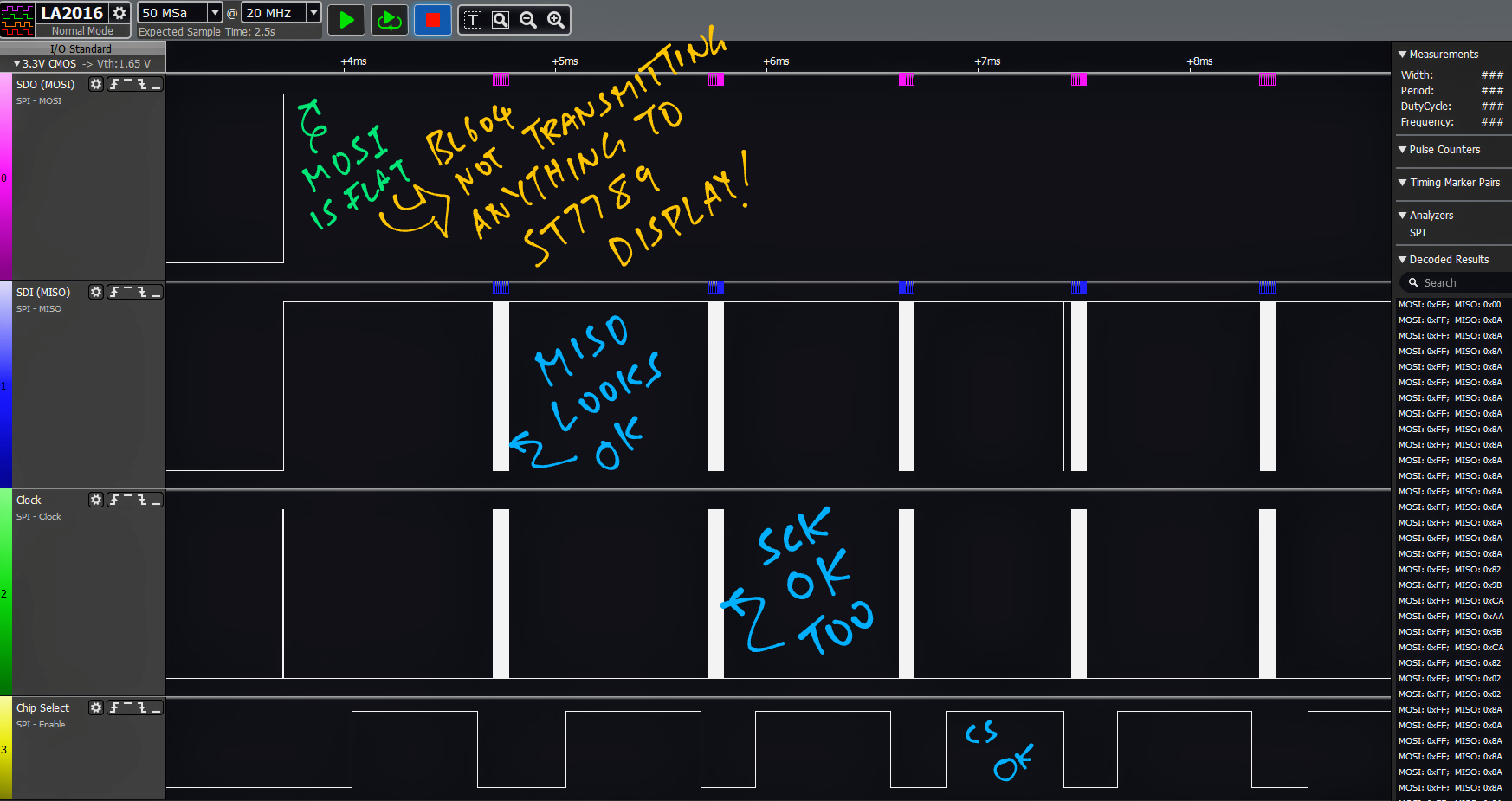
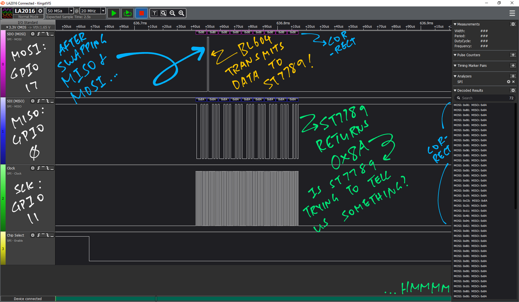
#BL604 doesn't seem to be transmitting anything to ST7789 on SPI MOSI (GPIO 17) ... Let's try a different pin for MOSI
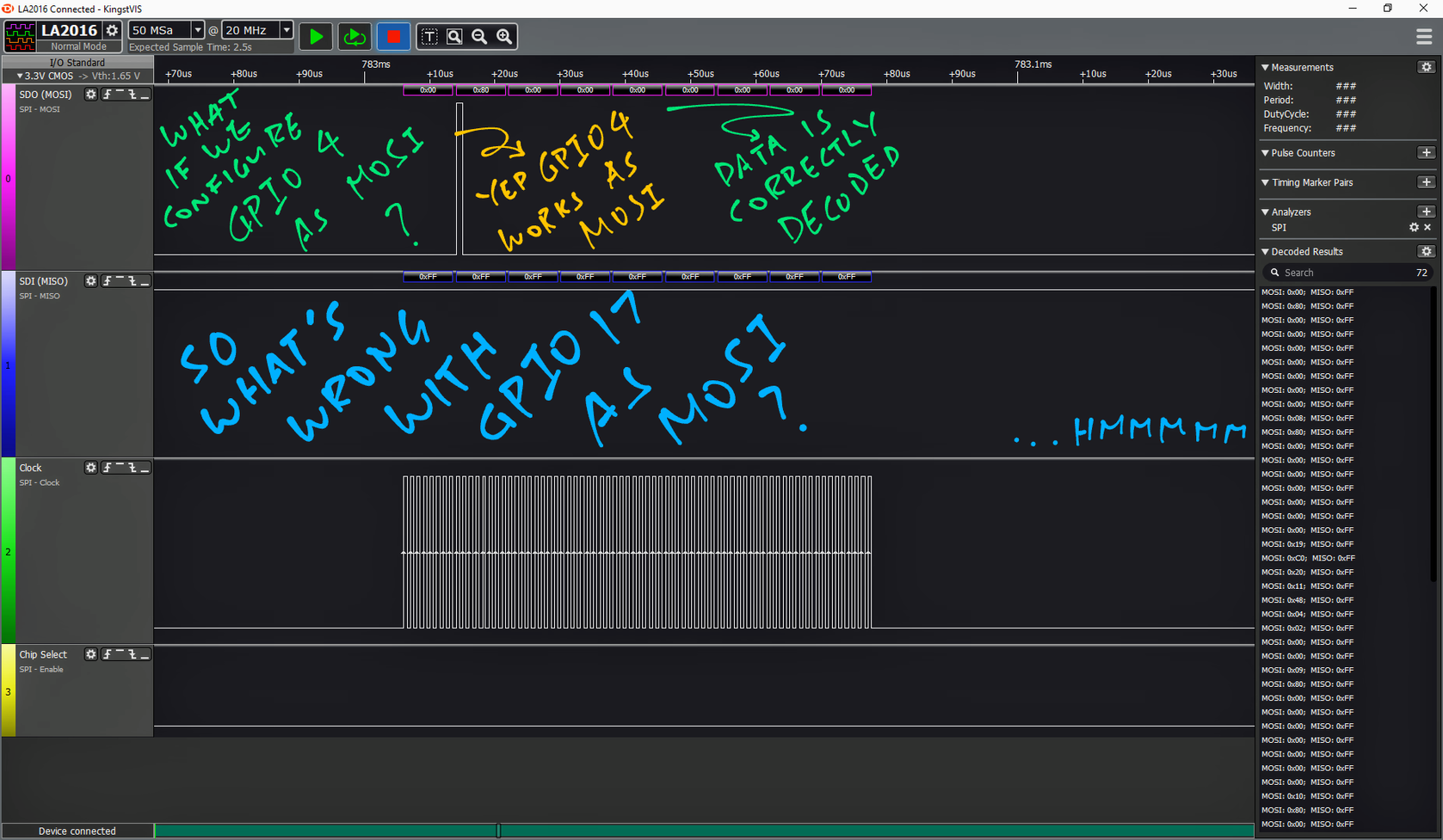
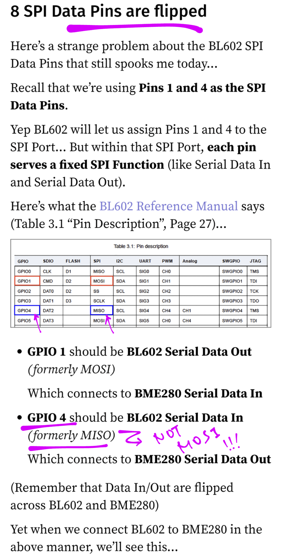
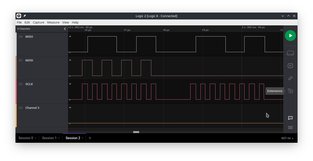
Yep #BL604 MOSI works if we switch to GPIO 4 ... So what's wrong with GPIO 17? 🤔
Which is super strange because GPIO 4 is supposed to be MISO on #BL604 ... Not MOSI! 🤔
https://lupyuen.github.io/articles/spi#spi-data-pins-are-flipped
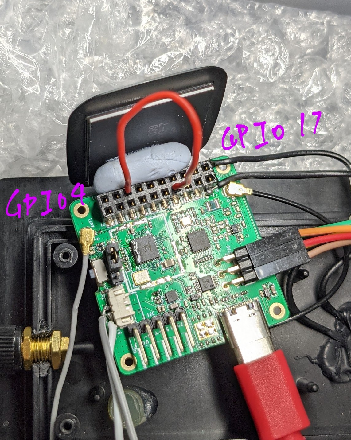
GPIO 4 works as MOSI but not GPIO 17 ... What if we connect GPIO 4 to 17? Nope still nothing on the #PineDio Stack ST7789 Display 🤔
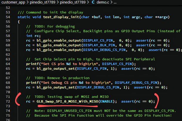
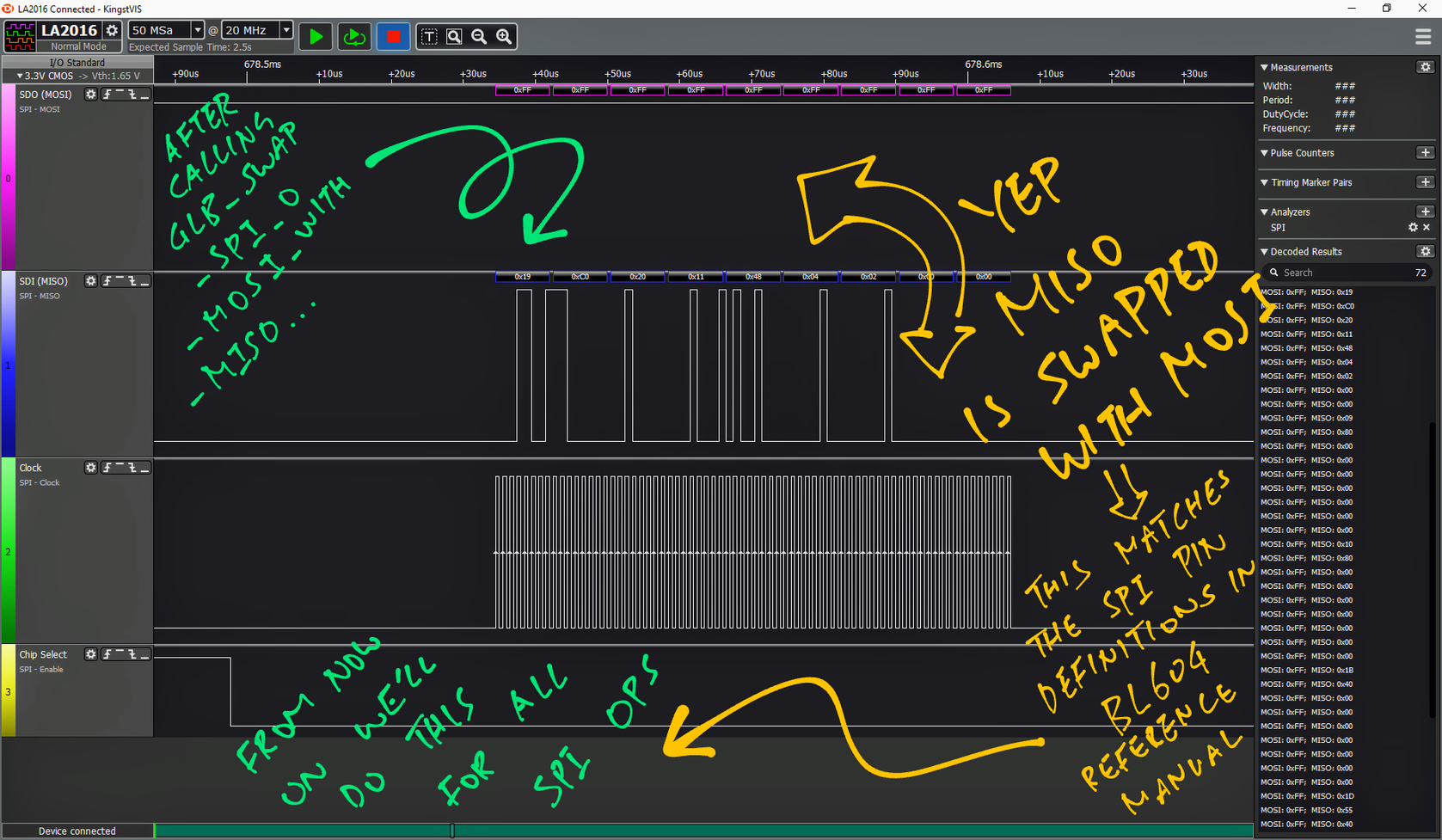
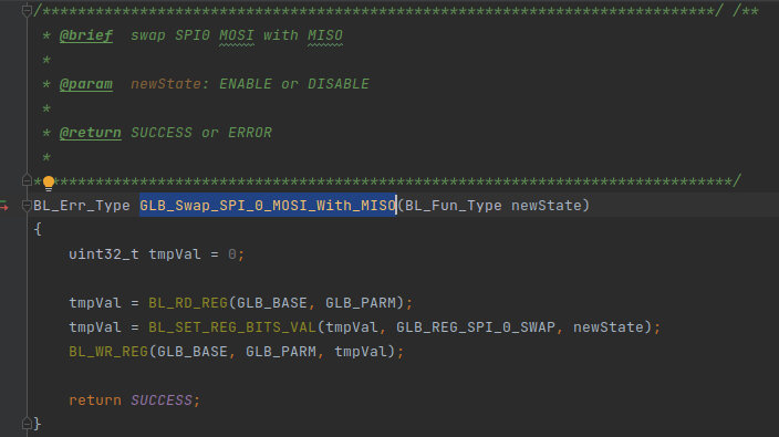
Yep MISO and MOSI are now swapped! This matches the SPI Pin Definitions in #BL604 Reference Manual ... So from now on we'll always call GLB_Swap_SPI_0_MOSI_With_MISO
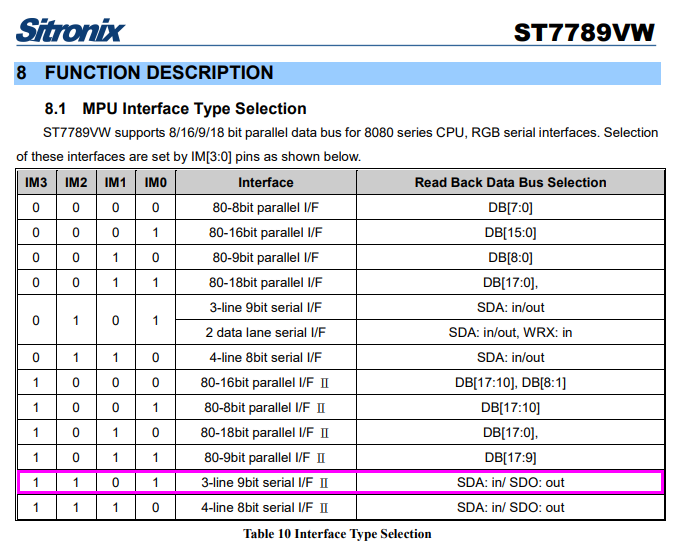
Need to verify that our #ST7789 Display is hardwired for "3-line 9bit serial I/F Ⅱ" mode: IM0 = 1, IM1 = 0, IM2 = 1, IM3 = 1 🤔
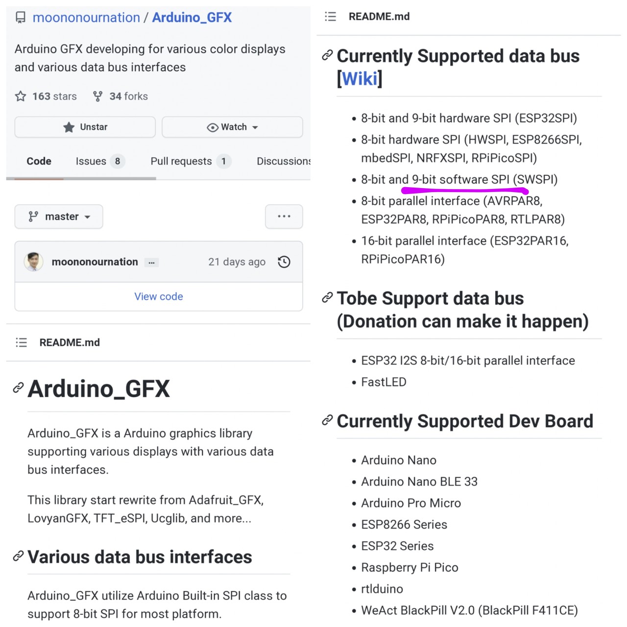
Let's port moononournation's awesome 9-bit-banging GFX Library to #BL604 ... And compare the SPI Output with a Logic Analyser
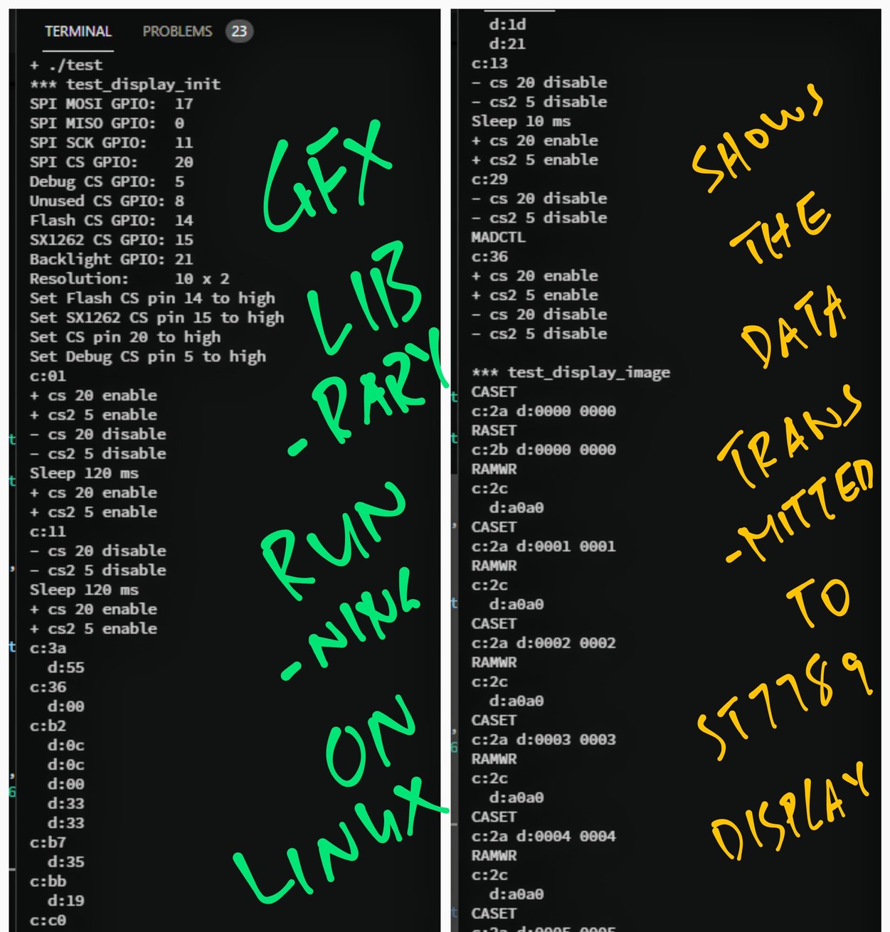
We run the GFX Library on Linux ... To see the data that will be transmitted to #ST7789 Display
https://github.com/lupyuen/bl_iot_sdk/blob/3wire/customer_app/pinedio_st7789_bitbang/test/test.c



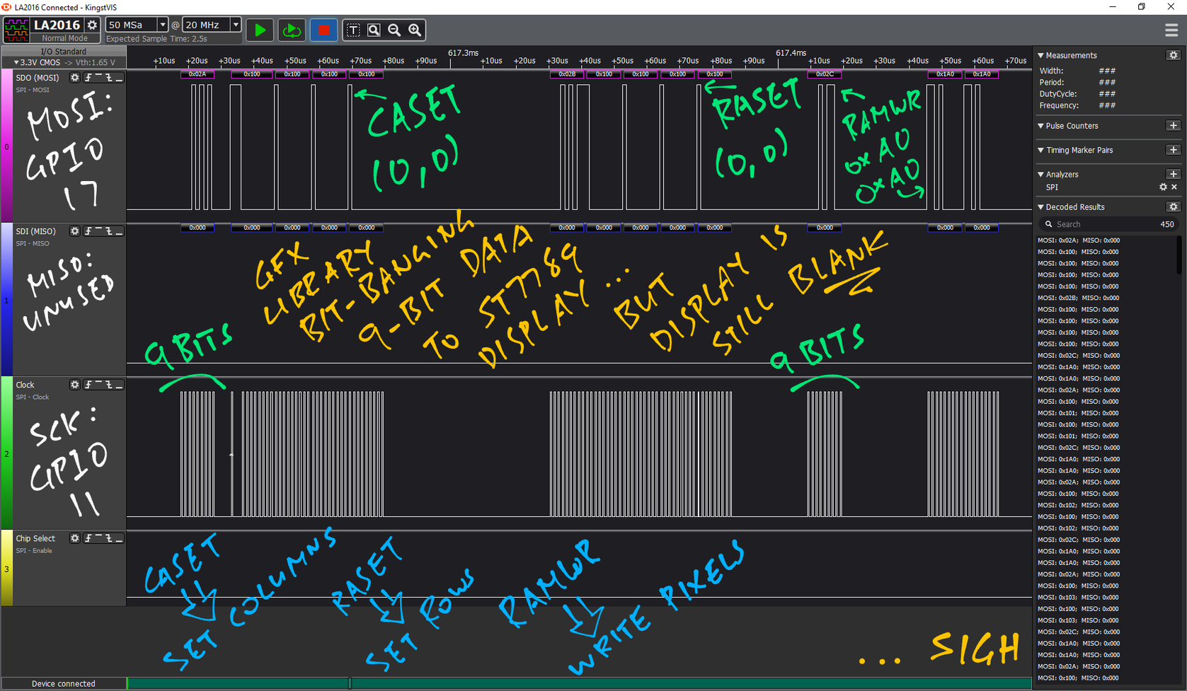

Packed #ST7789 9-bit data looks correct ... But nothing appears on #PineDio Stack Display 🤔
https://github.com/lupyuen/bl_iot_sdk/blob/3wire/customer_app/pinedio_st7789/pinedio_st7789/demo.c#L227-L2661